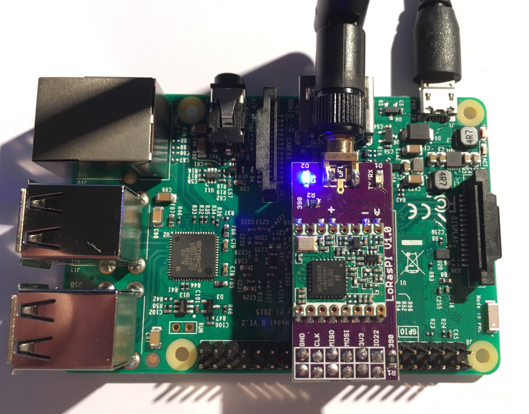
This shield is used to hold HopeRF Lora module Software with Raspbery PI. it has just few minimal features and it's working for TTN network.
I tweaked the Single LoraWan Gateway to get it working out of the box. It should also works with HAB Supplies Lora Gateway (same pinout), see this excellent Dave's article.
This shield can also act as a LoraWAN Node/gateway using this custom dedicated software
- RPI version of LMIC stack. This LMIC is working with this shield, see readme of repo.
- for RF69 networks using the excellent RadioHead customized library. This version is working with this shield, see readme of library.
As you can see, this shield is small but can do a lot but if you need a shield with more features (modules) on same board, I've designed a more featured one. It's called RPI Lora Gateway, you can go here to see it.
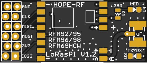
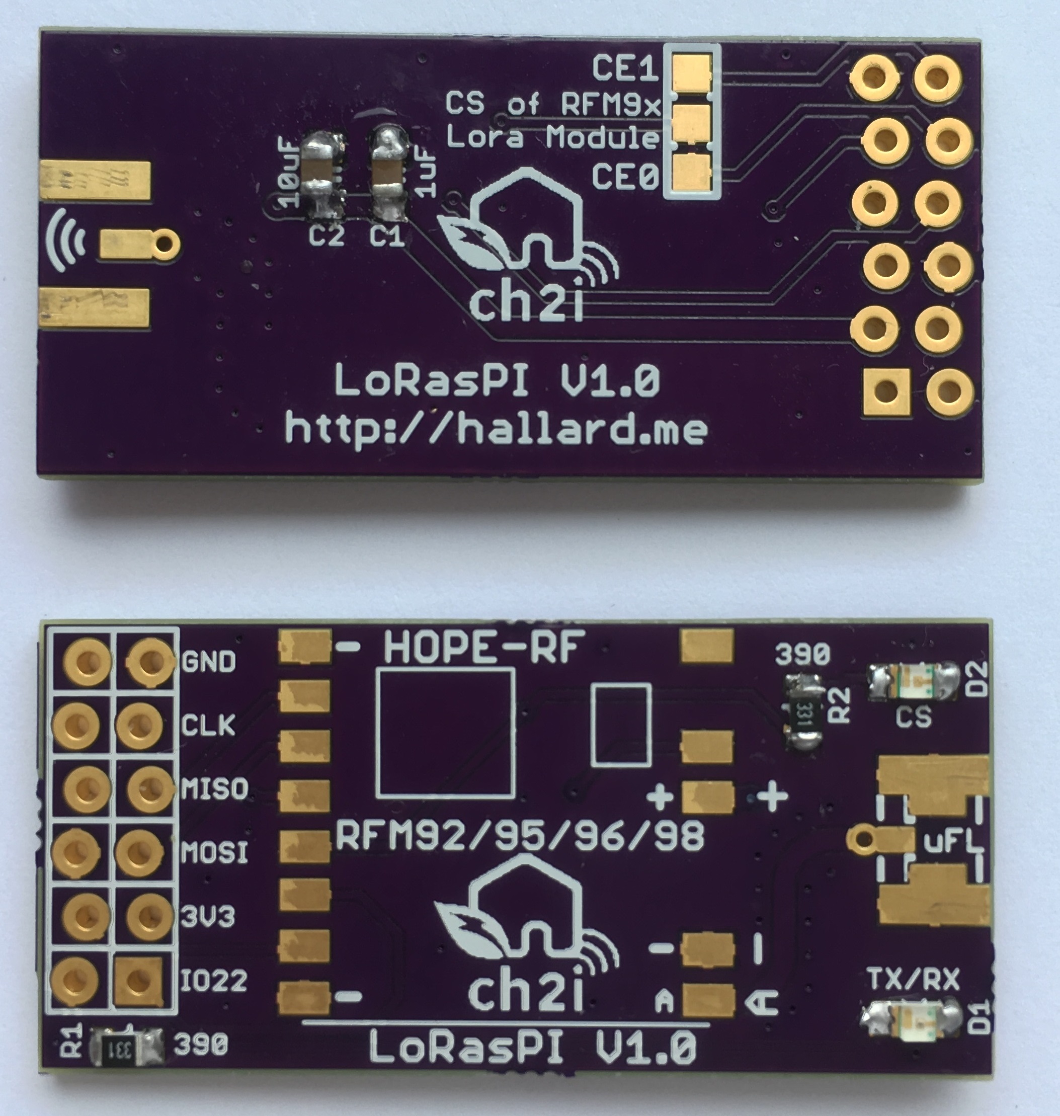
- Placement for RFM92/95/96/98 Lora module or RFM69HCW classic module
- Placement for choosing single Wire, SMA or u-FL Antenna type
- 2 x LED LED for visual indication
New in Version 1.2a
- V1.2 CS trace missing fixed
New in Version 1.2
- R3 Error corrected, it's now a Pull Down
- DIO5 connection to GPIO24 removed, not used
- 2nd led is now connected to GPIO24 instead of CS line
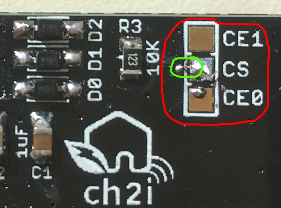
Error in V1.2, one small trace on CS (CE0 and CE1) signal is missing, fixed in V1.2a, I really apologize for this error, Eagle beginner error, ALWAYS place junction on schematic, because sometime it looks like connected but it's not!
Here is how to fix this V1.2 trace missing
With a small cutter or tool remove silk to bring via copper visible, then solder a tiny wire from CS pad to Via as follow (in green)
Just route the CE0 or CE1 signal with a small wire dirctly to RFM9x module as follow
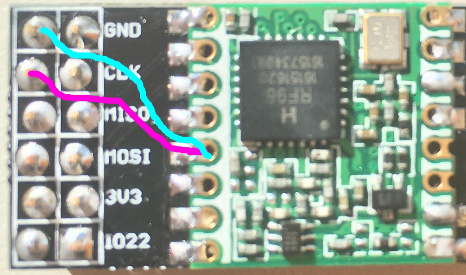 Use purple wire if you want to use CE0 and Cyan for CE1
New in Version 1.1
- Reduced board width so it can be soldered on 2x40 pins connector to expose other GPIOs
- Added DIO1 and DIO2 OR'ed with DIO0 and 1N4148 diode to conform LIMC stack
- Better ground plane isolation
- Added some via on RF part
I'm waiting now new V1.1 and V1.2 boards from OSHPark and PCBs.io, so I didn't fully tested V1.1/V1.2 yet, I will update ASAP.
I discovered a design error on V1.1, R3 resistor should be a pull down resistor and not a pull up, so you should not populate R3, do not place it, it's not a real problem since software will activate pull down of the BCM2835 controller but it's corrected in V1.2
I'm waiting boards V1.0 Boards arrived from OSHPark, all is working as expected (V1.0). so I didn't fully tested them yet, I will update ASAP.
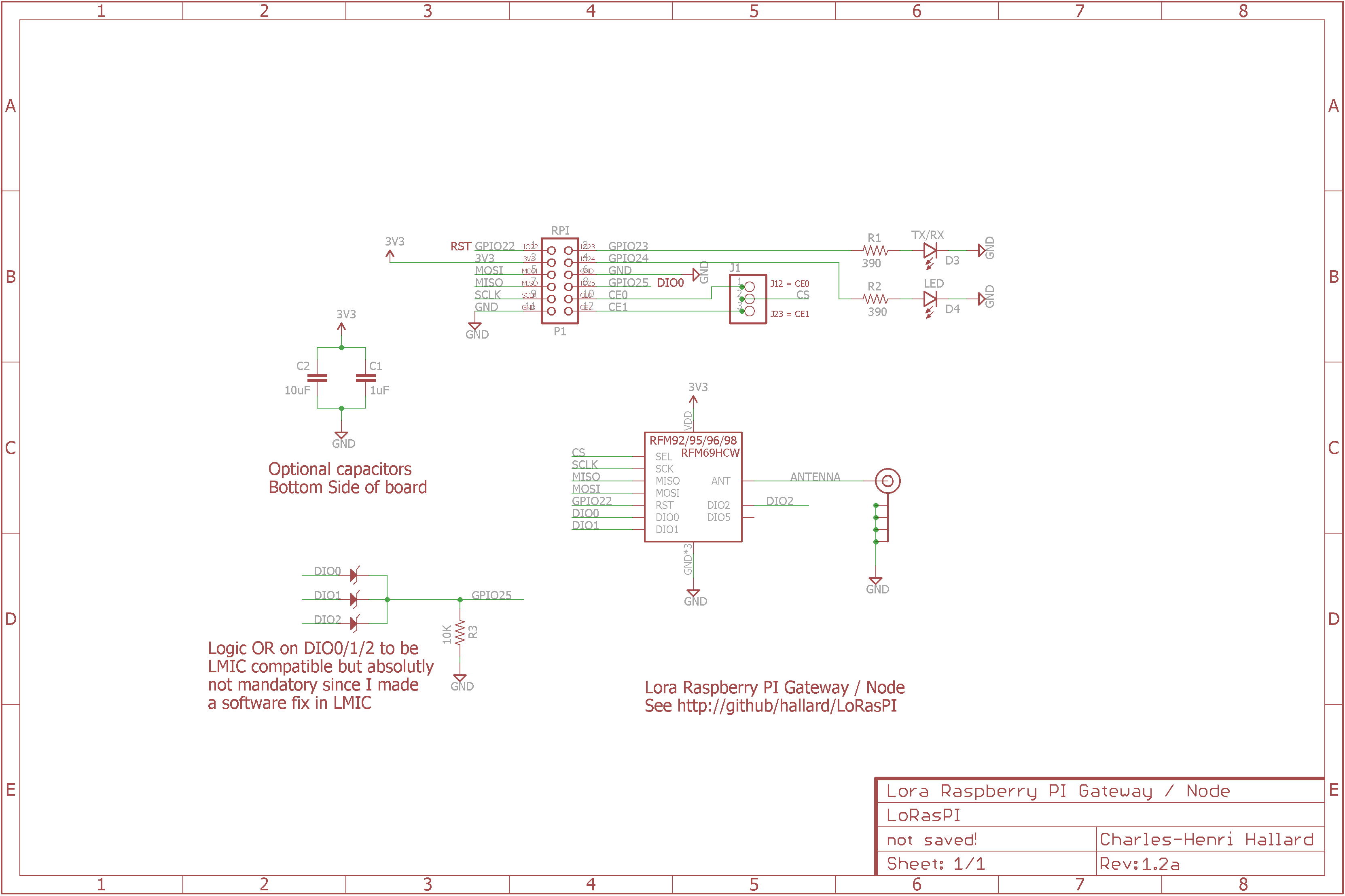
Look at the schematics for more informations.
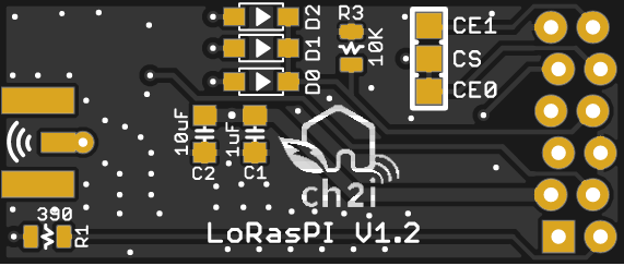
SPI connexion is classic (MOSI/MISO/CLK), Chip Select can be connected to CE0 or CE1 of PI depending on bord solder PAD jumper. Take care that by default it's connected to CE0 (wired) so you don't have to do anything. If you want to connect to CE1 you'll need to cut CE0 trace on the PCB (on the solder pad).
Only One GPIO needed for DIO0/DIO1/DIO2 (OR made with 3 diodes and one resistor R3) that will make this board fully compatible with current LIMC implementation, even if I've done a software fix which works with no interrupt. Only Needed for Lora modules, if you're using RFM69HCW and and to use IRQ just place D0 and R3.
Other pins that may need be adapted into code (for example if you use TTN network gateway code) according to the following pinout This Single LoraWan Gateway has been tweaked and works right out of the box.
Since V1.2
Raspberry PI   RFM9x Module 1
   GPIO22  <---->  Reset
   GPIO25  <---->  DIO0 OR DIO1 OR DIO2 (Hardware OR done with 1N4148 Diode and R3)

Raspberry PI   On Board LEDS
   GPIO23  <---->  LED D3 TX/RX
   GPIO24  <---->  LED D4 LED
V1.0 and V1.1
Raspberry PI   RFM9x Module 1
   GPIO22  <---->  Reset
   GPIO25  <---->  DIO0 OR DIO1 OR DIO2 (Hardware OR done with 1N4148 Diode and R3)
   GPIO24  <---->  DIO5 (Ready)

Raspberry PI   On Board LEDS
   GPIO23  <---->  LED D1 TX/RX
CE0 or CE1 <---->  LED D2 CS
V1.0 connected to Raspberry PI.
You can order the PCB of this board at OSHPARK (V1.1) or new V1.2a at PCBs.io. PCBs.io give me some reward when you order my designed boards from their site. This is pretty good, because I can use these rewards to create and design new boards and order boards for a discounted price and share new boards. So if you don't care about PCB manufacturer please use PCBs.io.
##License
You can do whatever you like with this design.
##Misc
See news and other projects on my blog
