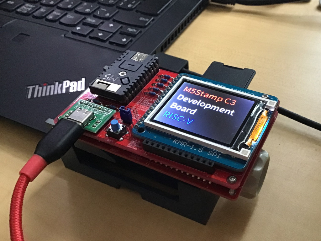
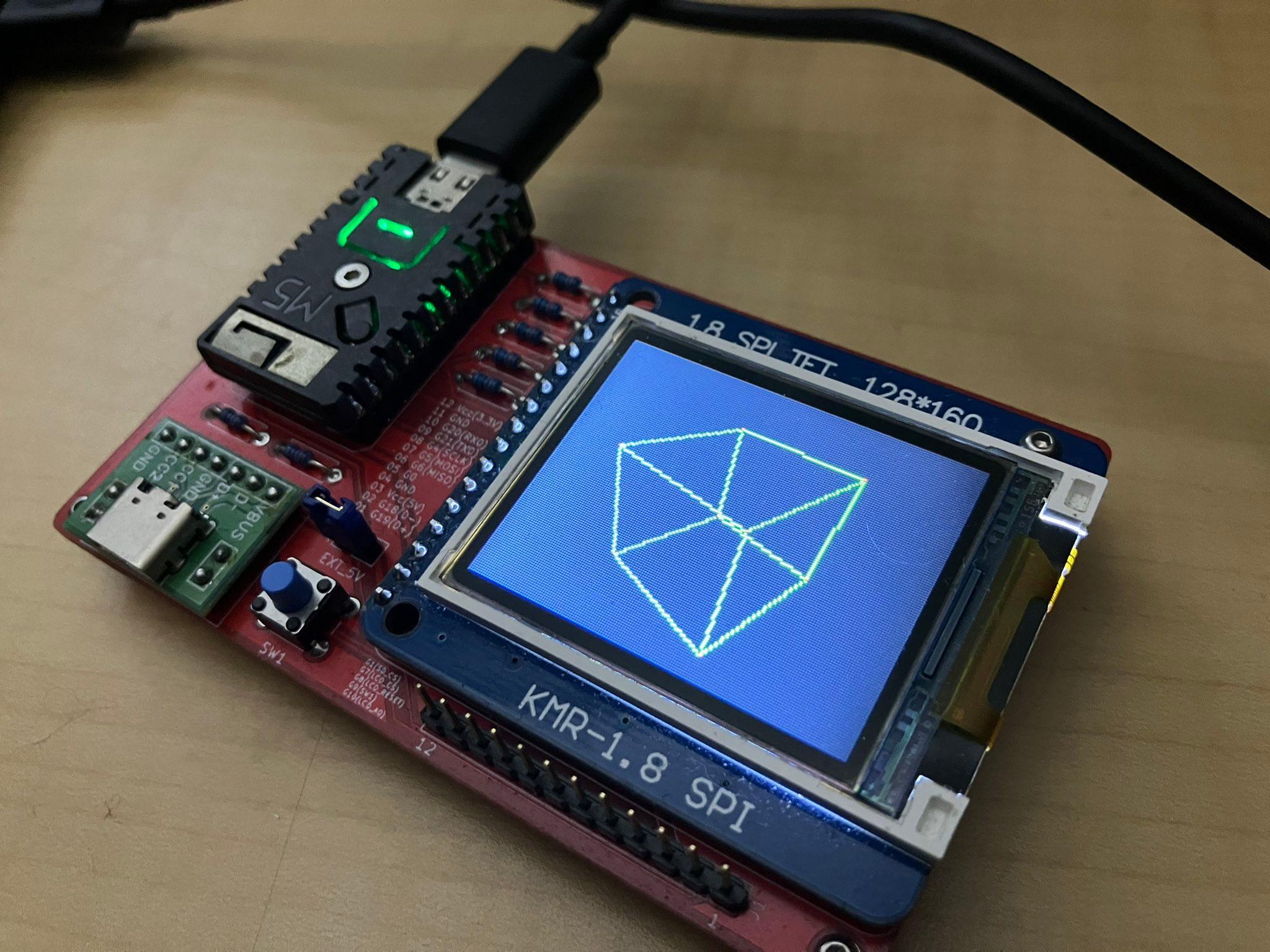
This is a development board for the M5Stamp C3 (RISC-V/FreeRTOS).
Hardware
- External USB-C port for JTAG debugging
- Support for LCD panel and SD card
- Selecting a power supply
- Switch(GPIO9) to enter loader mode
- Pin headers to expose usable GPIOs to the outside
- The size is just Japanese business card
Sample Sources Included
- TrueType font with Japanese output to LCD - test_freetype.cpp
- Output PNG images in SD card to LCD - test_tinypng.cpp
- NTP synchronization via WiFi connection - test_nvs_wifi.cpp
- Test ADC on GPIO0
- UNIT Light - main.cpp
- Test I2C on GPIO18, 19
- UNIT ENV III - test_i2c_gpio1819.cpp
- UNIT ULTRASONIC - test_i2c_gpio1819.cpp
- Test UART on GPIO18, 19
- UNIT GPS - test_uart_gpio1819.cpp
- WebAssembly execution with Wasm3
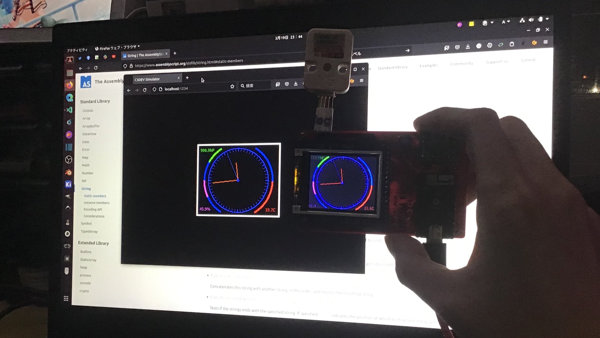
- Analog clock using AssemblyScript - test_wasm3_clockenv.cpp
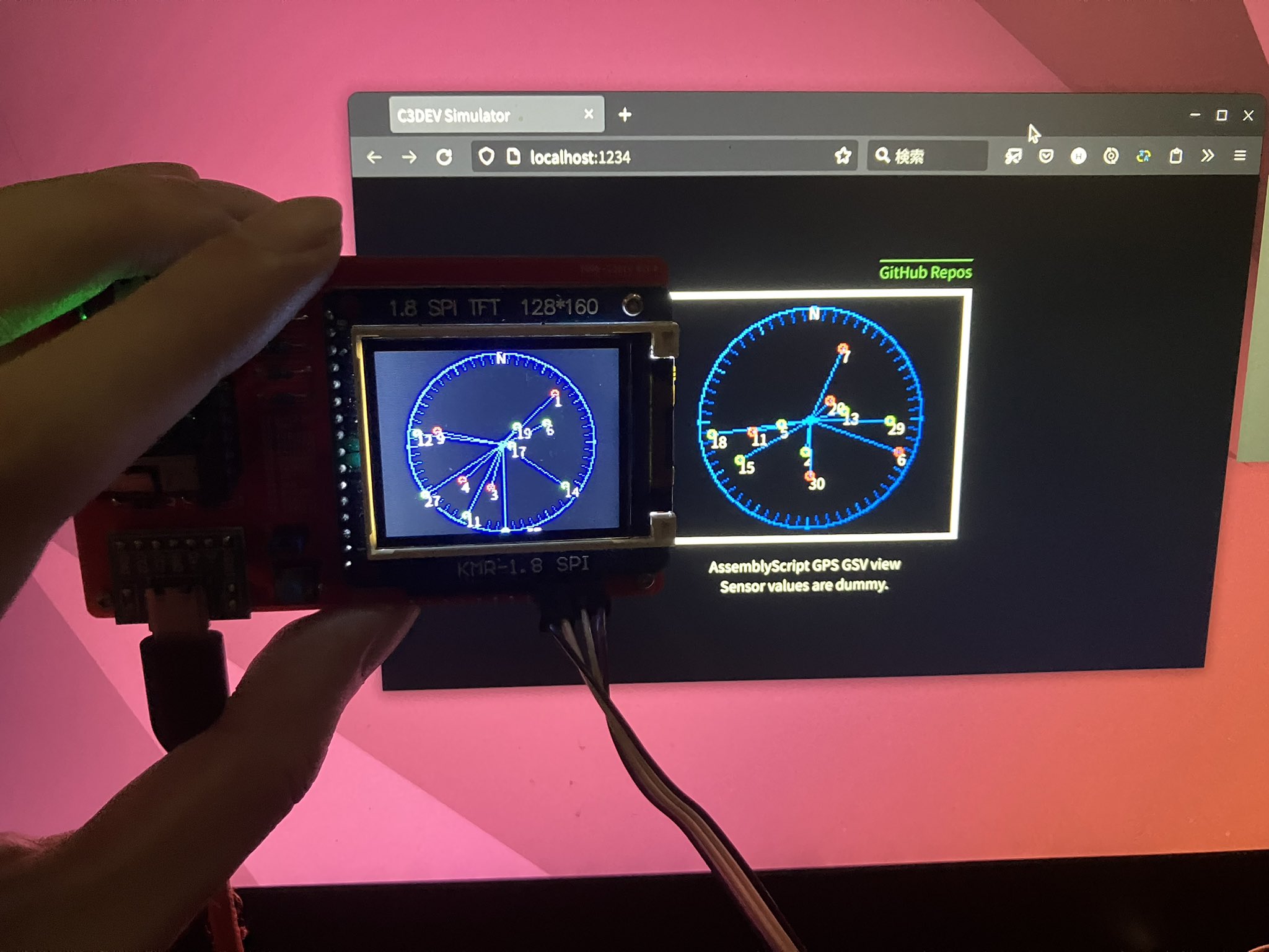
- GPS GSV viewer using AssemblyScript - test_wasm3_gpsgsv.cpp
- 3D Cube Demo using AssemblyScript - test_wasm3_imu6886.cpp
- Usage of SPIFFS, which stores TrueType fonts and .wasm binaries (parttool.py and spiffsgen.py tools)
- Use of NVS (cryptographically enabled key value store) that stores WiFi passwords (nvs_partition_gen.py tool)
- Building libraries and managing dependencies using the esp-idf build system
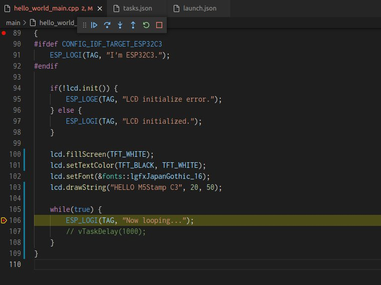
- Visual Studio Code C/C++ Extension configuration and JTAG debugging configuration in conjunction with openocd
- AssembyScript sharing method between web browser and microcontroller - wasm
This repository contains MIT Licensed PCB data and example programs.
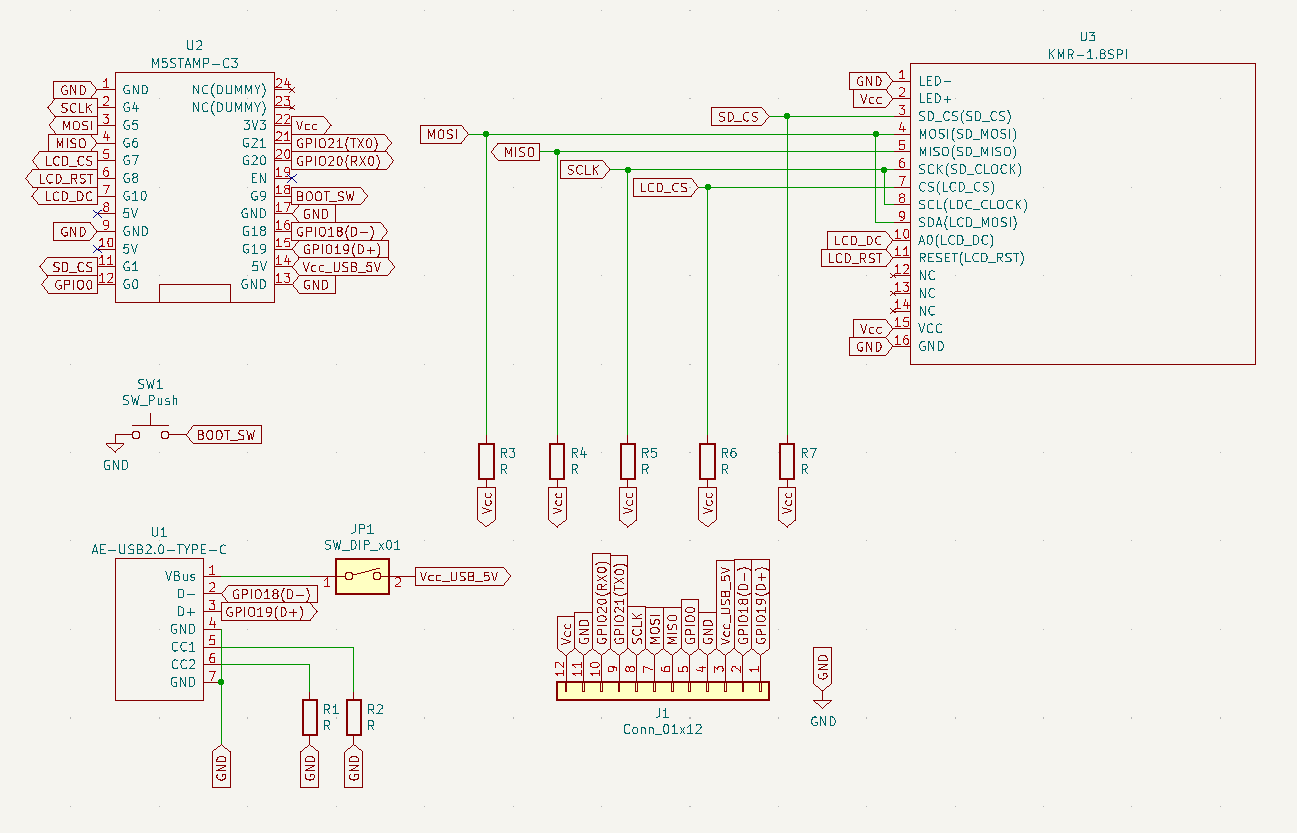
| #Unit | Name | Note | Where to get it |
|---|---|---|---|
| U1 | AE-USB2.0-TYPE-C | USB 2.0 Type-C Break out board | akizukidenshi.com (JP) |
| U2 | M5STAMP-C3 | M5Stamp C3 | + M5Stack + SWITCH SCIENCE (JP) |
| U3 | KMR-1.8SPI | KMR-1.8 SPI marked LCD and SD card interface | + amazon.co.jp (1) + ja.aliexpress.com |
| R1 - R2 | 5.2K Resistor | Pull-down for USB Power supply | - |
| R3 - R7 | 10K Resistor | SPI pull-up | - |
| JP1 | Jumper pin | Select external power supply | akizukidenshi.com (JP) |
| SW1 | Tact switch | for loader mode and utility | akizukidenshi.com (JP) |
| J1 | 12 Pin header | You can use the one that comes with the M5Stamp C3 Mate | - |
get_idf or (Windows) ESP-IDF command prompt
# Linux or macOS ->
$ alias get_idf='. $HOME/esp/esp-idf/export.sh'
$ get_idf
# <-

Detecting the Python interpreter
... snip ...
Done! You can now compile ESP-IDF projects.
Go to the project directory and run:

  idf.py build

$ echo ${IDF_PATH}
/home/hiromasa/devel/toolchain/esp/esp-idf

$ riscv32-esp-elf-gcc -v
Using built-in specs.
COLLECT_GCC=riscv32-esp-elf-gcc
... snip ...
gcc version 12.2.0 (crosstool-NG esp-12.2.0_20230208)
openocd (Optional)
$ openocd -v
Open On-Chip Debugger v0.12.0-esp32-20240318 (2024-03-18-18:25)
Licensed under GNU GPL v2
For bug reports, read
        http://openocd.org/doc/doxygen/bugs.html
- git clone and build (Please add
--recursive)
git clone --recursive https://github.com/h1romas4/m5stamp-c3dev
cd m5stamp-c3dev
idf.py build
Note: If you get a compile error, change the sdkconfig back to the Git one. In some cases, the target of sdkconfig is changed to esp32 instead of eps32c3.
- Write Partition table
idf.py partition-table-flash
- Write TypeType font to SPIFFS
parttool.py write_partition --partition-name=font --partition-subtype=spiffs --input resources/spiffs_font.bin
- Write WebAssembly(.wasm) to SPIFFS
parttool.py write_partition --partition-name=wasm --partition-subtype=spiffs --input resources/spiffs_wasm.bin
- Write main program to go!
idf.py flash monitor
- Change WiFi Setting
nvs_partition.csv: Set own [ssid], [password]
key,type,encoding,value
wifi,namespace,,
ssid,data,string,[ssid]
passwd,data,string,[password]
- Create NVS Partition file
python ${IDF_PATH}/components/nvs_flash/nvs_partition_generator/nvs_partition_gen.py generate nvs_partition.csv nvs_partition.bin 0x6000
- Write NVS Partition
esptool.py write_flash 0x9000 nvs_partition.bin
- Run
NTP synchronization is performed by pressing the SW1 after the startup logo.
idf.py monitor
idf.py menuconfig
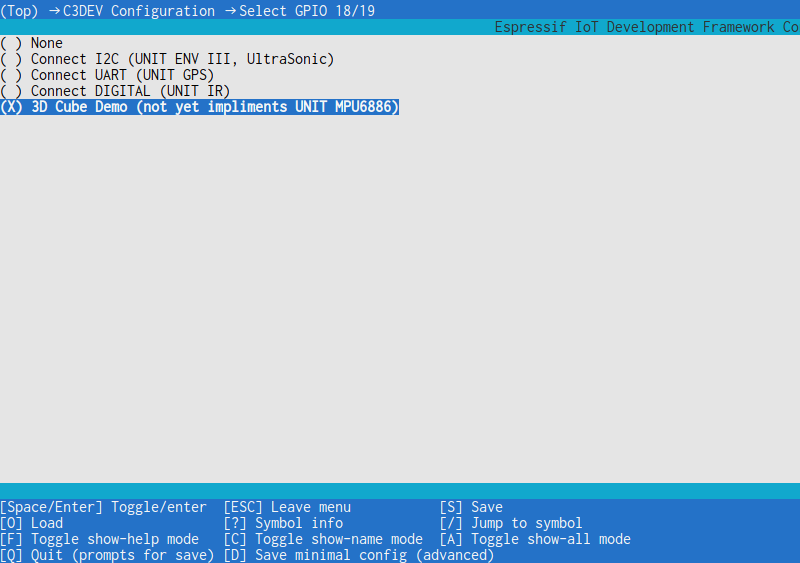
C3DEV Configuration → Select GPIO 18/19
3D Cube Demo
Require setup ESP32_TOOLCHAIN_HOME
$ echo ${ESP32_TOOLCHAIN_HOME}
/home/hiromasa/.espressif/tools/riscv32-esp-elf
- Connect the PC to the USB Type-C of the U1
- Open the source file in Visual Studio Code.
- Run Task "openocd (debug)" @see .vscode/tasks.json
- Set a breakpoint in the source code.
- Debug Launch (GDB) @see .vscode/launch.json The first time you start the program, it will often fail, so if you get an error, retry.
main/main.cpp
    // If the color is inverted, set to 1.
    tft.invertDisplay(0);
// tft.invertDisplay(1);python ${IDF_PATH}/components/spiffs/spiffsgen.py 0x100000 resources/font resources/spiffs_font.bin
python ${IDF_PATH}/components/spiffs/spiffsgen.py 0x10000 resources/wasm resources/spiffs_wasm.bin
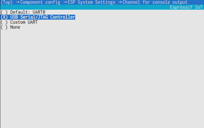
Component config → ESP System Settings → Channel for console output
idf.py menuconfig
cd wasm/clockenv # or wasm/gpsgsv or wasm/imu6886
npm install
Web Browser Development
npm run asbuild:web
npm run start
# http://localhost:1234/
SPIFFS Build and Flash
npm run asbuild
cd ../../
python ${IDF_PATH}/components/spiffs/spiffsgen.py 0x10000 resources/wasm resources/spiffs_wasm.bin
parttool.py write_partition --partition-name=wasm --partition-subtype=spiffs --input resources/spiffs_wasm.bin
Thanks for all the open source.
| Name | Version | License |
|---|---|---|
| esp-idf | release/v5.1 |
BSD License |
| arduino-esp32 | 3.0.2 |
LGPL-2.1 License |
| M5EPD | 0.1.5 |
MIT License |
| UNIT_ENV | 0.0.7 |
MIT License |
| M5Unit-Sonic | 0.0.2 |
MIT License |
| Adafruit_GFX | 1.11.9 |
BSD License |
| Adafruit_BusIO | 1.16.1 |
MIT License |
| Adafruit-ST7735-Library | 1.10.4 |
MIT License |
| tinyPNG | 0.11 |
MIT License |
| lwgps | v2.1.0 |
MIT License |
| Wasm3 | master(045040a9) |
MIT License |
| AssemblyScript | 0.27.29 |
Apache-2.0 License |
| 源真ゴシック | - | SIL Open Font License 1.1 |
MIT License (includes PCB data and example source)
